I use QGIS and Digital Elevation Models (DEMs) as a basis for culvert design work. When I need to take that DEM data into Civil3D, there’s a catch!
Civil3D can create surfaces directly from a DEM, and I was clipping a small portion of my (very large, county-wide) DEM from QGIS to import into Civil3D. I also used MAPIMPORT in Civil3D to bring in some linework from QGIS shapefiles (SHP). But things just didn’t line up quite right – the linework was always shifted slightly and didn’t match the DEM.
After scratching my head for hours/days/months, I finally found the reason why through the Autodesk Knowledge Forums and a fellow who goes by @pointdump.
It turns out that Civil3d creates a surface from a DEM by placing a point at the corner of each DEM pixel, rather than the center. That subtle decision changes the surface just enough that it doesn’t match up. @pointdump also provided the solution:
Rather than creating the Civil3D surface using the DEM directly, use QGIS to create points at the center of each pixel in the raster. A QGIS tool does this and creates a field in the attributes of the point SHP file that has the elevation. This data can then be used in Civil3D to create a surface that will match up with other imported linework and geolocated data in Civil3D.
Here’s how to do it step by step:
- Create the DEM .TIF in QGIS. I’ve also added 1-foot contours that will be imported to Civil3D to show the difference in how Civil3D creates DEM surfaces. Use the two highlighted tools in the Processing Toolbox to create a set of points from the DEM, and to add X-Y coordinates to the points.
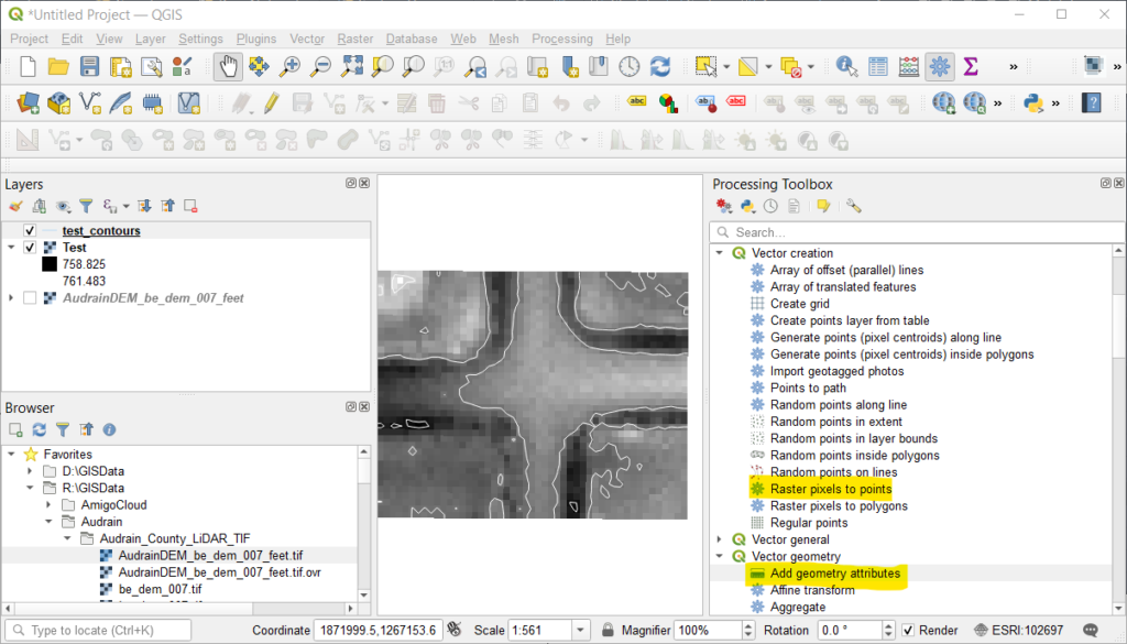
- First, use Raster to Points to create a temporary layer of points at the center of each pixel. Then use Add Vector Geometry to create a second layer containing the points and attributes for the X-Y coordinates. The default settings for both tools are fine. If you choose to change any of the field names, the instructions below must be altered accordingly.
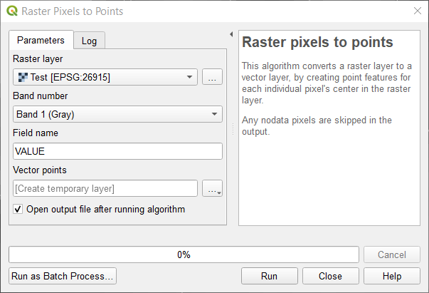
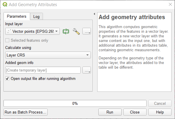
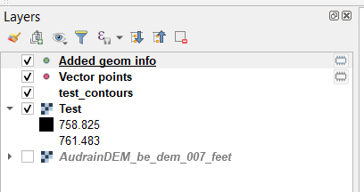
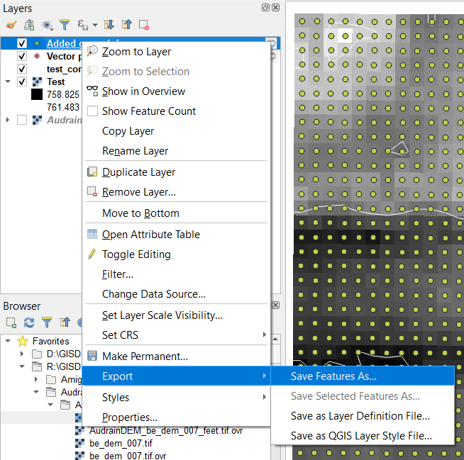
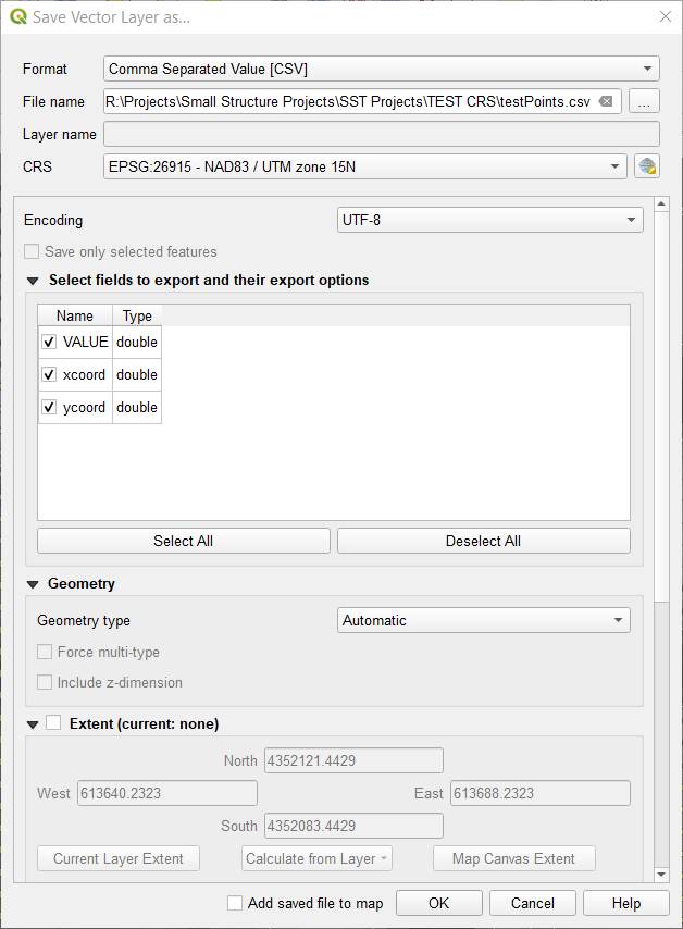
- There are now two new layers – Vector Points and Added geom info. Use the second layer and Export to save a new CSV file. Notice the field names that will be created: VALUE, X, Y. Also notice the Coordinate Reference System (CRS) of the points – this will be inherited from the CRS of the original DEM. In my case, the DEM was in EPSG:26915 – NAD83 / UTM zone 15N – Projected. This will create a CSV file with a header row containing the field names (VALUE, X, Y) and a row with elevation and coordinates for each pixel of the original DEM. The CSV point file is ready for creating a Civil3D surface.
- Create a new surface in Civil3D. Under Definition, choose Point Files and right click to Add. Choose the point file created from QGIS in dialog – but there’s something missing. Civil3D needs a point file format matching the format of our new CSV point file.
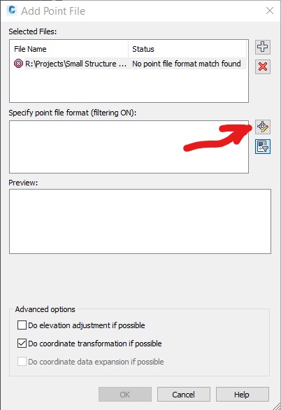
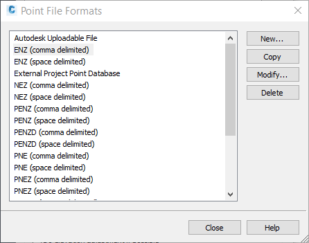
- We need to create a new point file format – this is done by copying, then modifying, an existing point file format. Click the button to select from a list of point file formats. Choose one and then Copy. A new dialog will appear. Give the new format a descriptive name and change the default file format to .csv. The Comment Tag field is used to filter any rows that are not actual points – in our instance, the header row, which starts with VALUE.
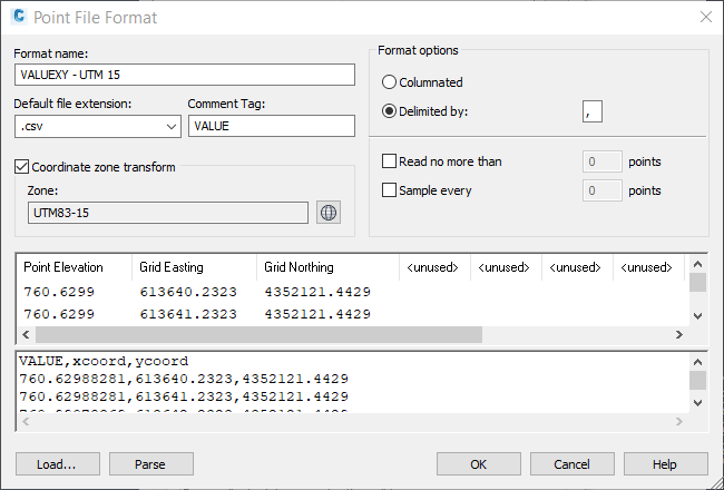
- The point file CRS may be different from the Civil3D CRS. The point file format allows selecting the CRS for the points – Civil3D will then handle the different coordinate systems for us. Check the Coordinate zone transform box, then select the CRS corresponding to your point file. In my case UTM83-15 is the same as the EPSG:26915 of my original DEM. Important: EPSG:26915 is a metric coordinate system, so the CRS chosen for the point file must also be metric. If your imported data is in the wrong place – check the units!
- The next step is matching the imported point columns to match the data in our CSV point file. We have VALUE, X, Y (where VALUE is the elevation), so the first three columns should be Point Elevation, Grid Easting, and Grid Northing. The remainder of the columns in the point file format are unused. The dialog allows loading a point file, then parsing the columns to make sure everything is working correctly.
- Close the dialogs to get back to the Add Point File dialog and, if the CSV file has been selected, the Preview should show the first few points.
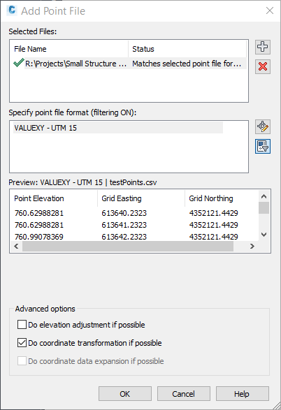
- Make sure to check the Do coordinate transform if possible checkbox, which tells Civil3D to use the CRS selected for the point file format. Click OK to create the new surface.
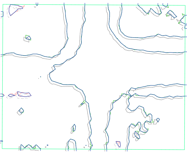
The image below shows contours from two surfaces in Civil3D and demonstrates the difference in results from how Civil3D creates surfaces from DEM’s. The first (gray contour lines)is a surface created by importing the DEM directly. The second is from the CSV point file. The second surface (red and green contour lines), from the point file, will match up with other linework imported from QGIS – the first does not.
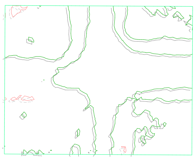
The same surfaces, with the contour SHP file from QGIS imported as blue lines. The QGIS contours are directly overtop the point file surface contours.
